


this is a dangerous hobby. It's probably not for everyone. If you are underage, you should obtain adult consent and supervision before attempting to build or operate a turbojet engine. Please read the FAQ for more safety information.
I have always been fascinated by all things mechanical, and all things powerful. Gas turbine engines (jet engines) fall into both categories. During my endless hours surfing the net I've come across many pages about home built turbine engines, and have considered building one myself. However, I was worried that I didn't have the necessary tools, skills, and money to pull it off. I am primarily a wood worker. I don't own a metal cutting lathe or a milling machine, and I can't weld. I am also chronically short of cash. These factors prevented me from seriously persuing the idea at first.
As I found more and more examples of home built turbines on the net, I realized that there was a great variation in the level of sophistication. Some were built by master machinists, and looked it. Others seem to have been banged together with only the aid of a hacksaw and a hammer. Whether finely crafted, or crudely thrown together, they all worked. I began to believe that I could also build one, and started to make plans.
I decided I would try to build an engine only from parts that could be obtained easily and cheaply. They would come primarily from auto scrap yards and hardware stores. The engine must be designed so that I can build it with my limited skills, tools and funds. I also decided that the engine should do something useful, and not just make lots of noise and heat while burning up lots of fuel. My ultimate goal is to add a second turbine, and extract energy to run a generator or do something else useful. But before I could get fancy, I first had to actually build a working engine. This is a chronicle of my efforts.
My further developments page chronicles the ongoing modifications and experimentation with the completed engine.
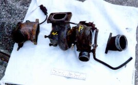
 This is my $50 turbo charger. The car it came off of had 114,000 miles on it, and the bearings are in pretty bad shape. I'm not going to worry about them for now. This is my "learner turbo", once I really know what I'm doing I'll have it rebuilt or buy a better one. |
Today I found a turbo charger at Copher's You-Pull-It for $50. It came off of an 83 Nisan Pulsar Turbo. This turbo charger was not chosen because it is the best one for the job. It was chosen because it was the easiest to remove of all the turbo chargers in the scrap yard. The turbo was mounted on top, and in front of the engine, where it was "easy" to get at. Even so, It took me three hours of hard work under the blazing sun to remove it. I took nearly every tool I own with me, but forgot my sun screen. Ouch, sunburn. The car had 114,000 miles on it, but the turbo seems to be in good shape. There is some play in the bearings, but I'm not sure how much is too much. I'm going to hope it's ok.
I kept my eyes open for something to use as an oil pump while I was at the scrap yard. I may try a
power steering pump. I can get one very cheap and easy. I can also get 12 volt fan motors to drive it.
I'm working on ideas for the combustion chamber and flame holder.
07/17/99
Decided to try to make the combustion chamber out of standard pipe fittings. I Bought some 2 inch
steel pipe and fittings. Also bought some 1.25 inch steel conduit to use as a flame holder. The
combustor will be long, skinny, funny looking, and heavy as hell, but I believe it will work. Total
cost, about $20.
I decided that the engine should ultimately run on liquid fuel, probably alcohol. However, I will probably do the initial combustor tests with propane, because it's just so much easier.
07/24/99
After a few false starts, today I had a brainstorm about the flame holder, and began working on it.
My idea is to flare the turbine end of the tube out to the inside diameter of the combustion chamber.
This will force the air to pass through the tube rather than simply blow around it.
The conduit is harder to work than I expected, but it is slowly coming along.
 This is the flame tube. It is made from 1.25 in. steel electrical conduit. The fuel injector passes through the hole on the right. The turbine end is flared out to the inside diameter of the air case. The four slots left from flaring act as the last set of dilution holes. |
While working out the size and placement of the air holes in the flame holder, I was struck by an amazingly obvious thought. The flame holder tube is smaller in diameter, 1.25in, than the outlet from the compressor, 1.5in. This means (duh) that no matter how many holes I put in the flame holder, it will still partially obstruct air flow through the combustion chamber. Is this bad? I'm not sure, but I suspect it could be a problem.
The process of flaring the flame holder tube left 4 triangular slots at the turbine end. I had planned to completely close these slots with metal shims. Now I think I will make the shims adjustable so that excess air can be dumped behind the flame tube. No-doubt it will take a lot of experimentation to determine the optimum placement of the shims for best operation.
09/05/99
Spent some time working on the combustion chamber this morning. It's been too stinking hot lately to
spend any length of time working in my garage. This morning was a little cooler than usual, so I
managed to get in a couple of hours before the heat of the day.
The combustion chamber, flame holder, and fuel injector are all essentially completed. All that's left to be done before I can test it is to settle on an ignition system. I haven't decided just what to do about that yet. I go back and forth between using a traditional spark plug, and a somewhat untraditional brainstorm I had about striking an arc directly to the fuel injector. It's too hot for more work today, so I'll just think about it for a while.
I bought some high pressure hose and fittings today so I can get propane from the tank to the fuel injector.
Progress will be slow until cooler weather arrives.
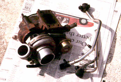
 This is the completed combustor. The fuel inlet is on the right. The air inlet is on the lower right. The spark plug is at the top. The exhaust is through the flange on the left. The combustor is built entirely from standard pipe fittings. Four new holes have been drilled in the flange to mate with the bolt holes on the turbo. |
At last, slightly cooler weather. I have finally come to a decision about the ignition. I have decided to use a conventional spark plug. There are enough unknowns with this engine already. I want to go with something tried and true for the ignition.
Today I bought a small motorcycle spark plug. With some difficulty I managed to drill and tap a hole for it in the heavy pipe of the combustion chamber. I also drilled a passage hole for it in the flame holder. I have an old LASER power supply that will make a nice hot arc across the plug gap.
I need to build some sort of test stand so I can test the combustor soon. The blower from my shopvac can provide air, and I have propane tanks, high pressure hose, and fittings. All I need to do is put it all together.
09/21/99
I had the day off work today because of tropical storm Harvey. The storm missed me, but blew in a cool
perfect day for working on the engine.
 This is my makeshift test stand for the combustor. The injector end of the combustor is facing the camera, and the air blower is on the left. |
I spent a good while plumbing together the fuel line and fittings. I also had my spare propane tank refilled. I'm almost ready to test. Just a few more odds and ends need to be completed. I have a very busy weekend ahead of me, but perhaps I can find the time to do a test run or two.
It's going to take guts to fire this thing up. It's mean looking, and real loud just with the blower running. I suspect there will be a very loud bang when it ignites, and it will probably really roar when it's burning. I wonder how my neighbors will react?
09/24/99
Today I attempted the first test run of the combustor. I could not achieve ignition no matter what I
tried. Even with really unreasonable, and scary, amounts of propane, nothing happened.
I have formed several theories about what problems could be causing this, and how to fix them.
- 1. The blower is producing too much airflow causing a too lean condition. The blower does produce a very large airflow, more than I expected. I may mount a bleeder valve between the blower and the combustor to reduce the airflow.
- 2. Too many and/or too large air holes in primary zone causing a too lean condition I will try closing down some of the holes.
- 3. Spark not hot enough. Looking into the combustor with the blower and ignition on I can see that the spark is flickering and on the verge of being blown out entirely by the air blast. I will build a robust plug-in power supply for the ignition system and get rid of the wimpy batteries.
- 4. The hole pattern in flame holder may not be producing enough turbulence to adequately mix the propane and air. I may try to angle some of the holes in the primary zone to produce some swirl.
09/25/99
I made some modifications today. I have closed down some of the primary air holes. I have also built
the plug-in power supply for the ignition system.
Success! Ignition was achieved easily. There was no loud bang as I had feared. Ignition is like turning on a fire hose. It burns with a very loud low frequency rumble that brought the neighbor lady running to see what was happening. The rumble comes from instability in the combustion. Combustion will not self-sustain, and the flame blows out immediately if the ignition is switched off. I suspect that there is not enough turbulence to produce adequate mixing of the propane and air. There is also only a very narrow region of fuel pressure where it will burn. A little above or below, and the flame blows out. My next modification will probably be to try to induce swirl inside the flame holder.
looking into the open end of the combustor while it's burning requires standing nearly 20 feet away, but even so the air blast is amazingly hot and powerful. I think I have created a monster. The flame is pale blue, and seems to be entirely contained in the combustor.
I wobbled out some of the holes in the primary zone in such a way as to hopefully induce some swirl. I did another test run in the early evening. There was no noticeable difference in the performance. Under the darker conditions I did notice that the flame extends several inches beyond the end of the combustor. I am beginning to suspect that the injector is a big part of the problem.
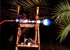
 This is a test firing of the completed combustor after dark. This photo is a several second exposure taken to capture the flame. The flash was fired at the end of the exposure to illuminate the rest of the scene. |
I made some modifications to the injector in an effort to get better mixing of the propane and air. Another test run showed perhaps slightly better combustion stability. However, the flame still won't self-sustain. I'm going to work on a totally new fuel injector design and add a needle valve to the fuel system to try to get better control of the propane pressure. Up till now I've been using the valve on the tank to control the pressure. It's a rough adjustment to say the least.
I may also experiment with closing down the triangular slots on the flame tube. (I've been running with them wide open.) I want to force as much air as possible through the dilution holes to cool the combustion gasses before they leave the combustor.
 The original injector is on the left. The new one is on the right The new injector is a piece of 1/8 in. copper tubing smashed nearly flat. The opening is a very thin slit that is nearly invisible. |
What a difference a new injector can make. My first injector was a 1/8 in. brass hose barb. I tried to constrict it a little, but the thick brass was tough. The new one is a 1/8 in. copper tube smashed almost flat. The opening is an amazingly thin slit. The combustor ran much smoother with it installed. It still would not self-sustain, but it could be throttled over an amazingly large range of fuel pressures, 40-100 psi. It ran rough at the high and low extremes but fairly smoothly through the middle of the range. I ran the combustor for quite a while and explored it's characteristics, long enough for the propane tank to start sweating heavily. I then noticed that the HV power supply was badly overheating and starting to smoke. I then shut everything down to let it cool off.
When the combustor was cool enough to touch I tore it down. The last few inches of the flame holder are fairly discolored, but there is no sign of melting as I had feared could happen. Discoloration so close to the open end leads me to believe that the flame front is too far down the tube. This is probably why the flame extends past the end of the combustor. I decided to close down the triangular slots in the flame tube to see if that would cause the flame front to retreat toward the injector. After putting it all back together, it would not ignite. I seem to have the same condition that existed a couple of days ago. I assumed it was running too lean to ignite, so I put the old injector back in. I know that injector is providing a lot more propane, but it still won't ignite.
It's possible that the problem is with the HV power supply. It did really badly overheat, enough to burn my finger. It could be damaged. The spark plug is probably a much lower impedance load than it was designed for. I guess I will have to build a more traditional HV power source. I have several old auto ignition coils laying around. I'll build a driver circuit for one of them and try again in a few days.
 This is the new high voltage power supply for the spark plug. You can see it arcing away at the upper left. Don't laugh at the construction technique, it works. |
Last night I finished the new HV power supply.
Today I spent most of the afternoon trying to get back to where I was 09/27/99 before I started tinkering with the combustor. I hooked the new HV supply up to the combustor. No joy, it still won't ignite. I then put the second injector back in, still no ignition. Then I partially opened the slots in the flame tube, and was rewarded with some half-hearted chugging and puffing. I opened the slots some more, and it got better. I then removed the shims and opened the slots fully. Now it runs nearly as well as it did before. Obviously there is too much air going into the flame holder with the slots closed.
The combustor is still not ruining as smoothly as it was. I think my new HV supply is not producing an arc as hot as the old one was. The air blast is really doing a number on the arc. This would not be a problem if the flame would self-sustain, because it would only have to ignite once. The combustion got smoother as I opened the slots until they were all the way open. I suspect that there is still too much air going into the flame tube even with the slots all the way open. I can't open the slots any more, but I can close down holes in the flame tube. that will be my next project.
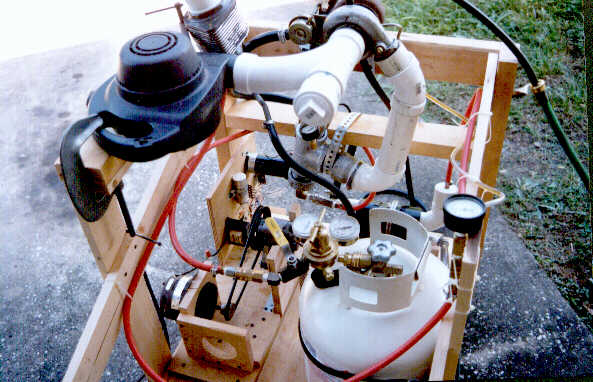
 The propane fuel tank with the new regulator that allows fine control of the fuel pressure. The yellow handle is part of a quick shut-off valve. It's come in handy a couple of times. |
Today has been a very productive day.
First I added a welding gas type regulator to the propane tank in an effort to get better control of the fuel pressure. I have noticed that as the propane tank gets cold during use the pressure drops. This makes it very hard to keep a constant pressure going to the injector. The pressure in the propane tank is so low that the high pressure gage never even moves off it's peg. Otherwise it works great. I wish I had thought of it earlier.
Next I tried a run with ALL the holes in the primary zone closed off. No good, could not achieve ignition, only some pathetic chugging. Next I opened 4 - 1/16 in. holes just beside the injector. The combustor ignited, but burned really roughly. I noticed that when I turned off the propane at the tank valve, the combustion smoothed out for a few seconds before the flame blew out.
This is when I made my big breakthrough. I started it up again then slowly reduced the pressure with the regulator. The combustion got really rough as I lowered the pressure. Suddenly, at about 38 psi the flame moved to the back of the flame tube and really smoothed out. There was no more of the rumble I was so used to. It was burning much smoother. It now roars like a high pressure air leak. I turned off the ignition, and sure enough it self-sustained. No wonder, when I stood well back and looked up the exhaust, I saw that the spark plug and all the little metal burrs around the holes in the flame tube were glowing bright orange. Even without the spark there were so many ignition sources that the flame couldn't possibly have blown out. I shut it down because I was afraid I would melt the spark plug. If I had not installed the regulator I never would have found the region of stable burning. Controlling the fuel pressure with the tank valve was just too touchy.
As it stands now, the fuel pressure must be brought up to about 60 psi before ignition is achieved. At 60 psi the combustion is rough and has the loud rumble of instability. After it's been burning at 60 psi for a few seconds, I can reduce the pressure to the stable area around 38 psi. The flame front retreats up the tube, smoothes out, and gets real hot. The flame seems to be burning well up the flame tube, and not extending past the end of the tube. I need to do another run in the dark to make sure.
I will probably enlarge the passage hole for the spark plug in the flame tube in an effort to blow more cool air on the plug. I suspect this will make the combustor more difficult to ignite. The air/fuel mix near the plug is already too lean to ignite unless the fuel pressure is really cranked up. The spark plug is probably too far away from the fuel injector. Unfortunately, moving the plug closer to the injector end would require a major redesign of the whole combustor.
In the early evening I did some more testing. I found that the combustor is very sensitive to injector orientation. With the slit in the injector in the same plane as the spark plug it will ignite. Turn it 90 degrees, and it won't ignite no matter what. In between it's iffy. I also found that the flame is indeed fully contained inside the flame tube at 38 psi. I decided not to worry about the spark plug, and let it run a while. After a few seconds I noticed the whole flame tube was glowing dull red. The plug and all the little metal burrs were again glowing bright orange. I tried throttling the combustor and found it burns very smoothly over an amazing range of fuel pressures once the flame tube is hot. It will burn smoothly and self-sustain from only a few psi up to just over 60 psi. Over 60 psi the flame becomes unstable and won't self-sustain. At low pressure it just whispers, but at 60 psi it really roars. The flame starts to peek out of the end of the combustor at about 45 psi. At 60 psi it roars like a space shuttle trying to take off, and has a nice tongue of pale blue flame extending several inches beyond the end of the combustor. I ran it at high power for several minutes just to see what would happen. No problems were observed. When I shut it down I could see that the entire length of the flame tube was glowing orange.
I pulled out the spark plug to see if it was damaged. Other than a slight discoloration of the metal, it looks just fine. I think I'll stop worrying about it, and leave modifications for the MK II engine.
10/03/99
I took the day off from working on the engine today and spent some time thinking about where to go
next. The combustor is essentially done. Now that I know how to properly start it up and run it, I'm
confident it will run a turbine.
When the weather gets a little cooler I'll return to the scrap yard to find the pieces I still need to finish the engine. I need an oil pump of some sort. An engine oil pump or perhaps a power steering pump will do. I'll need a motor to drive the pump. Perhaps a 12V radiator fan motor. I suspect I will need an oil cooler of some sort. I may even pick up an inter cooler and experiment with it if I can find one cheap and easy. It's been cool enough to fool around with the combustor on the shady side of my house, but not cool enough to bake under the sun in the scrap yard. Perhaps in a couple more weeks.
I'll need to build a framework to support all the bits and pieces. The test stand I'm using now won't cut it for testing the full blown engine. I priced some heavy duty metal shelving components a few weeks ago, but decided they were too expensive. I'll probably bang together something from 2X4s and plywood. I'll also probably put wheels on it to save my back.
I've also been thinking about how to extract power from the engine once I get it all together and running. Someone on the turbo turbine mailing list is using a homemade air motor running on compressor bleed air to power a generator. This is brilliant! No need to worry about high temp exhaust gasses, high speed reduction gearboxes, or precision balanced machinery. I'm not yet sure my engine will produce enough excess air to drive an air motor, but I could always use exhaust from the first turbo to drive a second turbo charger and use all the air from it's compressor. I'm going to be keeping my eyes open for a cheap air motor.
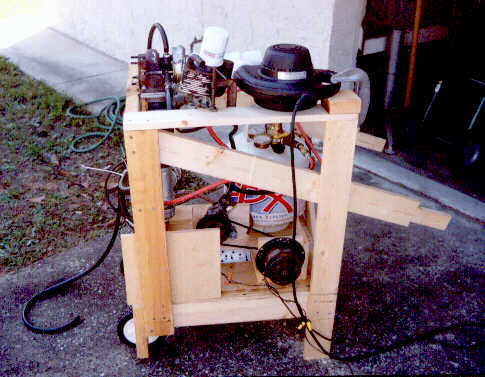
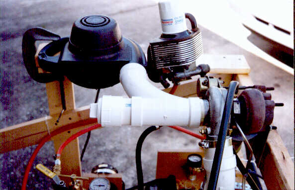
 Here is the "wheel barrow" type test stand for the engine. It will allow me to wheel it in and out of my garage. At the moment the only component mounted on it is the turbo charger. |
Today I started work on the test stand for the finished motor. It's just a simple wooden framework to support all the various parts in their proper configuration. I will probably put wheels on it eventually. For now it's sitting on a wheeled dolly in my workshop.
I have also made a tap in the side of the combustion chamber so I can read the pressure with a gage. This is just the first bit of instrumentation that I will have to build. Eventually I want to also monitor RPM, EGT, and fuel flow rate.
A machinist I work with has agreed to make an adapter plate to go between the flange on the combustor and the turbo. I decided that the flange is not really a very good fit on the inlet of the turbo, and some sort of adaptor is needed. It should be done sometime this week.
I also spent some time poking around the scrap yard today. I found some potentially useful bits, but didn't have the proper tools with me to remove them. I'll go back another time and try again.
10/16/99
Today I returned to the scrap yard with more tools and came away with some useful bits.
First I came across a power steering pump from a Toyota Corolla that someone else had already removed to get at some other bit. It was just hanging by the high pressure hose. Couldn't have been easier to remove. It cleaned up nicely, and now looks like new.
Next I saw an easy to remove transmission oil cooler and grabbed it. It's nothing fancy, just a mini radiator. I don't remember what type of car it came off of. I almost chucked it when I found the next bit, but decided to keep it anyway, just in case.
Lastly I removed a combination oil cooler and oil filter assembly from some sort of Mazda. It's a lovely little unit that kills two birds with one stone. I had been struggling with the problem of how to mount an oil filter. It bolted directly on to the top of the engine, so unfortunately there are no fittings for getting the oil in and out, only passage holes. I'll have to manufacture some sort of plate with fittings that I can bolt onto it. I kept the other cooler in case the job turns out to be too difficult.
Total cost, a little over $30 and a few cuts and bruises from slipping wrenches and sharp edges. I still need some sort of reservoir for the oil and some kind of motor to run the pump. I also need to do a lot of plumbing.
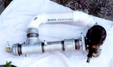 Here you can see the three main components of the engine mated together. The turbo charger on the right, combustor with it's spark plug, and PVC air pipe. |
Over the past busy week I've worked on the engine here and there where I could. The major components of the engine are now fully assembled. The combustor has been attached to the turbo via the new adaptor plate. The air outlet of the turbo has been connected to the combustor with PVC pipe and fittings. I'm worried that the PVC may blow off or soften at high boost levels, but I think I'll test it at low power as is. Most of my time has been spent mounting components on the now finished test stand. I've also mated the power steering pump with an old 120V AC fan motor. I've also worked out a way to attach hoses to the oil filter/cooler assembly I got from the scrap yard last week. The machinist who made the adaptor plate also gave me a small air tank made from large diameter PVC pipe to use as an oil reservoir. It will need major modifications before I can use it.
I still need to mount some components and do a lot of plumbing before I can do a test run.
10/24/99 - 10/27/99
The last few days I have been very busy, but have managed to get in quite a bit of work on the engine
in bursts of a few minutes to several hours. I have modified the PVC air tank for use as an oil
reservoir and mounted it on the test stand. I have also cobbled together a quick and dirty oil
pressure regulator out of lots of fittings and a needle valve. It will allow me to vary the oil
pressure to the turbo by bypassing oil around the the turbo when the valve is opened, or forcing the
oil through the turbo when the valve is closed. In theory, I should be able to adjust the oil pressure
quite precisely. Much of my time has been spent connecting the various components together with lots
of hoses. This thing is turning into a real plumbers nightmare.
There is only one major component left to mount, the oil filter/cooler assembly. It is a very awkward shape. After much brainstorming, I had the idea of making some mounting brackets out of aluminium angle that I can bolt onto it. I'll save that job for another day.
I am very close to being ready to test.
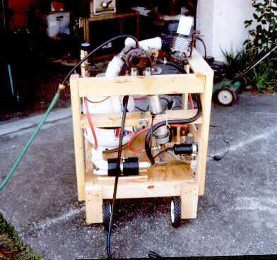
 A side view of the completed engine and test stand. |
It Runs! It Runs! Today has been a great day! I knew I was nearly ready to test, so my first stop after work today was the auto parts store. I bought 2 quarts of Mobil 1 5W30, an oil filter, and of course, more hose fittings. I had intended to spend much of the day making mounting brackets for the oil filter/cooler assembly. However, in a flash of insight, I realized that I could simply clamp it onto the test stand with a big C clamp, and get on with testing. After running a couple more hoses, I was ready to go.
The first attempt failed, but was a learning experience. Ignition was easy, and very smooth. The obstruction of the turbine must slow the airflow through the combustor enough to make ignition easier. As I throttled up the engine, it was responding well and spooling up. At about 3 or 4 psi of boost, the PVC air pipe blew off the combustor, and brought the test to a premature end.
|
|
I was surprised at how quiet the engine is when running. I had expected terrible noise, but it just whispers. The blower I use to start the engine is orders of magnitude more noisy than the engine itself. Once the engine is self-sustaining and the blower is off, the noise is not really that bad at all.
|
|
10/30/99
First thing this morning I modified the oil pressure regulator. Now it supplies from zero up to only a
couple of psi to the turbo. This works great. The engine starts right up very easily. It will
self-sustain from below 2 psi of boost up to above 7 psi. It will probably go higher, but without a
tach, I am afraid of over-revving it. The bearings are also in bad shape, so I don't want to strain
them too much.
|
|
I noticed that the turbine was running very hot on one run this morning. The turbine blades were glowing brightly. It doesn't normally run hot enough that the turbine can be seen to glow in daylight, so I looked around for a problem and found that the PVC air pipe was trying to blow off again, and was leaking air badly. It's interesting that the leak increased the EGT, but really didn't reduce the RPMs much. I shut down and reworked the pipe again. Now it is much stronger and sealed air tight. It could probably withstand several pounds more boost without further problems. Eventually a boost level will be reached where the air temperature (from the compression) is high enough to soften the PVC. Then I will have problems again. At 6-7 psi the pipe gets fairly warm to the touch, but not nearly hot enough to soften.
I also found that there is an air leak from the joint between the adaptor plate and the turbine inlet. Man o man is that some hot air coming out that leak. It is scorching the wooden frame of the test stand and has partly melted the water return hose from the turbo. I found the leak accidentally while running my hand along the air supply pipe looking for leaks. I jerked my hand back quickly and fortunately was not badly burned. After I demonstrate the engine to some of my friends, I'll tear it down for inspection, and when I reassemble it I'll use some high temp gasket material on those mating surfaces.
I am still amazed at how quiet the engine is. At 2-3 psi of boost it really runs very quiet. The sound it makes is like rushing air. Very similar to what you would hear driving at highway speed with the windows down in your car. The whine of the turbo is really only noticeable during acceleration or deceleration when it is changing pitch. Above 5 psi of boost the rushing noise gets loud enough to be irritating without ear protection if you are within a few feet of the engine. However, the noise is not loud enough to bother my neighbors further away. They didn't even know I had it up and running. The engine as a whole is quieter than the combustor alone was.
10/31/99
I ran the engine for quite some time today. I demonstrated it to friends, made a video of it in
operation, and ran it for about 15 minutes straight at 3 psi of boost just to see how stable it is.
It performed like a champ.
I also spent considerable time exploring the performance envelope of the engine. With a delicate touch on the fuel valve it can be made to run smoothly from just over 1 psi of boost up to about 5 psi. The response of the turbo is far from instantaneous, and it can't be throttled up or down too quickly. At 5 psi of boost and above I am seeing problems. I must have been lucky yesterday because today the rotor tends to start wobbling in its worn bearings above about 5 psi. This results in a rapid decrease in speed accompanied by loud and scary noises that I can't even begin to describe. When this happens the only thing to do is shut it down quickly. Because of this I have decided not to run it much above 4 psi anymore.
On the whole I am very happy with the engine. It starts easily, runs smoothly, and is much quieter than I expected. I will continue tweaking, improving, and adding instrumentation to it. I may also try adapting it to liquid fuel. However this little engine has only whetted my appetite for more power. Now that cooler weather has arrived I'll be haunting the scrap yards looking for turbo chargers that are larger and in better condition.
The goal of this web page was to describe the design, construction and testing of a primitive turbine engine. Now that the engine is up and running, I think that goal has been achieved. In the process, this page has gotten quite long and cumbersome. Making it any longer with reports of further developments on the engine is probably not a good idea. All further developments related to the engine can be found on the further developments page.
[Mike's homepage]
[Mike's telescope workshop]
[Mike's gold prospecting page]
[Mike's home-built wind turbine page]
[Mike's Home-Built Solar Panel page]